Home > Working with Planning Projects > Building an Application > Deployment and Workflow > Allowing Users to Extend Models
Allowing Users to Extend Models
Last Updated 2/28/2012 7:41 PM
Measure Modeler and Node Modeler are special access rights that can be granted to a user, which allow them to dynamically extend relevant parts of the model.
Measure Modeler rights allow a user to extend the measure rules, adding new measures and calculations if required. The changes will apply only to the node deployed to that user, and will not affect nodes deployed to other users. This allows different users to extend the measure logic in different ways. As an example if we deploy our Revenue model to such that Lucie has Restaurants, and Jack has Automotive Divisions, then each of them will be able to define their own measures and calculations as extensions to the base Revenue model.
Node Modeler rights allow a user to insert additional nodes under the node deployed to them. Let's say for example, that we deploy Restaurants for Australia to Mark, but Mark wants to create further nodes under Australia for Sydney, Melbourne and Brisbane, all we need to do is give Mark Node Modeler rights and he will be able to create the additional nodes for the three cities, which would then consolidate into Australia.
Using Measure Modeler
A user can only access the Measure Modeler feature if the owner of the Project has granted Measure Modeler access rights to them. Access can be granted through the deployment module (see Deploying Models for Input and Review to see how to grant access rights to users).
If a user has been granted Measure Modeler access, when they open the model in the Input folder and navigate to an input slice, an extra button appears on the toolbar  . .
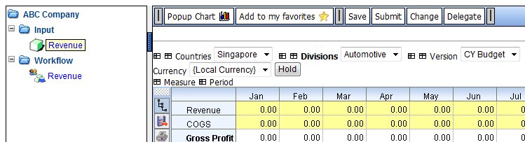
Clicking on the button opens up a window where we can extend the existing logic.
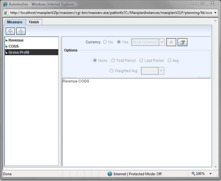
The original model logic created by the owner of the model is displayed. We cannot change any of the model owner's existing calculations, but we can add new measures and calculations, and we can add calculations to existing measures that don't already have any calculation associated with them. In the example shown above 'Gross Profit' already has a calculation associated with it, but 'Revenue' and 'COGS' are both input measures, which we can redefine as calculated measures.
Let's suppose that Jack, wants to extend the measure logic as follows:
Add new measures-
'Luxury Car Sales'
'Utility Vehicle Sales'
'Dealer Margin % Luxury Cars'
'Dealer Margin % Utility Vehicles'
Redefine 'Revenue' and 'COGS' input measures as calulations-
'Revenue' = 'Luxury Car Sales' + 'Utility Vehicle Sales'
'COGS' = 'Dealer Margin % Luxury Cars' * 'Luxury Car Sales' + 'Dealer Margin % Utility Vehicles' * 'Utility Vehicle Sales'
The steps would be as follows:
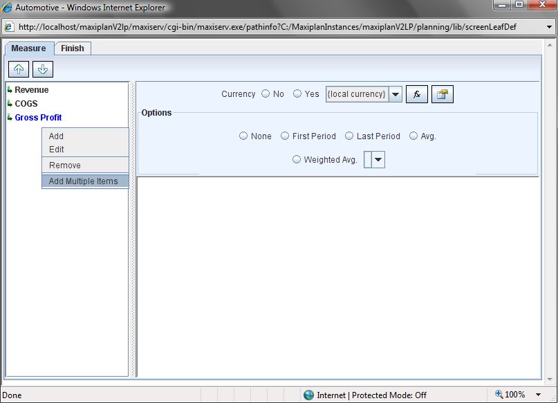
1. Add the new measures. We can do this by right clicking on the measures list on the left and selecting the option we wish to use. As we will be adding multiple measures we will use the 'Add Multiple Items' option.
2.Another popup window will appear where we can enter in the additional measures. Just enter them in without the single quote characters as MaxiPlan will add these in for you automatically.
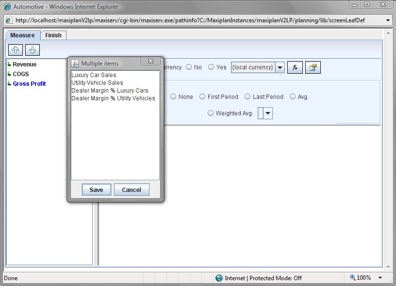
3. When you have entered the new measures, click on the  button and the new measures will be added. button and the new measures will be added.
4. Next we need to add the calculations for the 'Revenue' and 'COGS' measures. To add a calculation to a measure, select the measure you wish to add the calculation to ('Revenue' for example) and then click the  button which will open the measure calculation popup window. The bottom part of the popup is the expression window and shows the calculation, and in the top half on the left is a list of the measures we have available to use in our expression,and in the middle is a list of mathematical operators we can use, and finally on the right hand side is a list of special functions available. Using the mouse I can select and then drag the members into the expression window. Similarly I can select and drag any of the arithmetic operators or functions to the expression window. To select an item click it once. To drag a selected item click it again and drag it to whereer you want it to be in the expression window and release the mosue button. You can select multiple measures at once by holding the CTRL key down whilst you select multiple items, or to select a range you can select the first item and then hold the SHIFT key down while you select the last item in the range. button which will open the measure calculation popup window. The bottom part of the popup is the expression window and shows the calculation, and in the top half on the left is a list of the measures we have available to use in our expression,and in the middle is a list of mathematical operators we can use, and finally on the right hand side is a list of special functions available. Using the mouse I can select and then drag the members into the expression window. Similarly I can select and drag any of the arithmetic operators or functions to the expression window. To select an item click it once. To drag a selected item click it again and drag it to whereer you want it to be in the expression window and release the mosue button. You can select multiple measures at once by holding the CTRL key down whilst you select multiple items, or to select a range you can select the first item and then hold the SHIFT key down while you select the last item in the range.
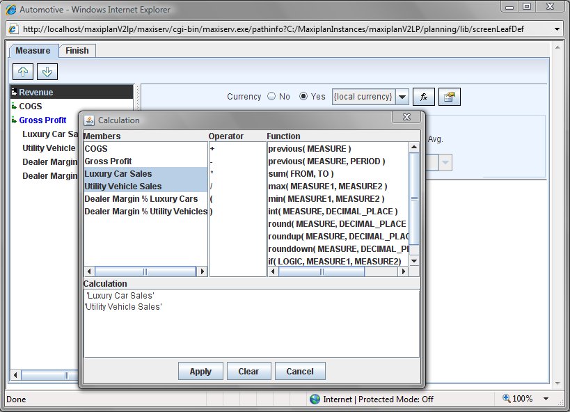
We could add in the '+' operator, but whenever we place a list of items into the expression window, if we don't specify any calculation, the system will assume that we wish to aggregate the selected measures.
Click on the  button to apply the expression to the selected measure. Once we have added the 'Revenue' calculation, we then follow the same process to add the 'COGS' calculation, except of course the calculation rule is different. button to apply the expression to the selected measure. Once we have added the 'Revenue' calculation, we then follow the same process to add the 'COGS' calculation, except of course the calculation rule is different.
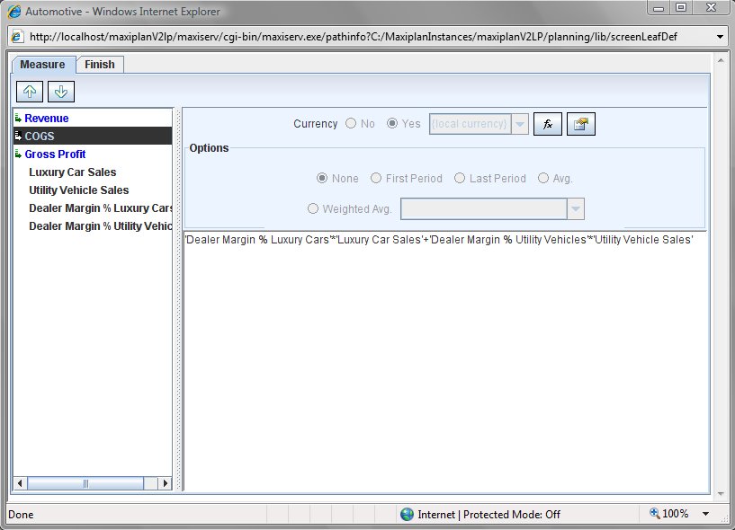
5. The final step is to select the 'Finish' tab and click on the  button. This will save your newly created additional logic. The window will remain open after the save, but you can close it by clicking the X symbol in the top right hand corner of the popup window button. This will save your newly created additional logic. The window will remain open after the save, but you can close it by clicking the X symbol in the top right hand corner of the popup window  . .
Viewing the Modified Model
To view the impact of the changes, you will need to refresh the model view by clicking on the model name again under the Input folder (it is necessary to do thsi so that the java based model viewer refreshes with the changes).
Using Node Modeler
A user can only access the Node Modeler feature if the owner of the Project has granted Node Modeler access rights to them. Access can be granted through the deployment module (see Deploying Models for Input and Review to see how to grant access rights to users).
If a user has been granted Node Modeler access, when they open the model an extra button appears on the toolbar  . .
Clicking on the button opens up a window where we can extend the deloyed node.
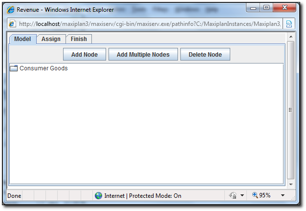
The deployed node is displayed and we cannot change it. However, we can add child nodes to it.
To add a child node, click on the  button. button.
To add multiple child nodes, click on the  button. button.
To delete a child node, click on the  button. button.
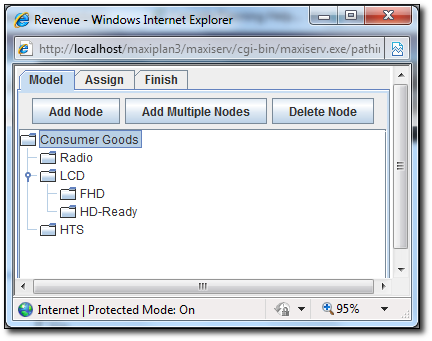
Let's assume that we want to extend the nodes as follows:
Radio
LCD
FHD
HD-Ready
HTS
We would do the following:
1. Open up the Extend Node screen.
2. Click on the button.
3. Enter the nodes as defined.
4. Put FHD and HD-Ready under LCD node.
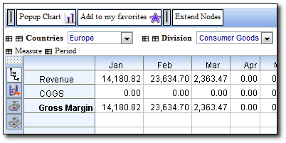
You will get the similar results to the screen below.
Now we can proceed to assign the child nodes to other users.
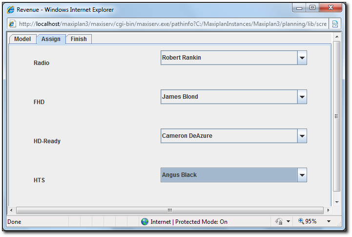
5. Click on the Assign tab in the Node Modeler screen.
6. Assign child nodes to users. (note: only the bottom most level nodes are assignable)
Once done, click on the Finish tab and click on the  button to save the settings. button to save the settings.
See also
| 

 Page URL: